Adelaide T&E Systems
 

Product - Human Thoracic Surrogate (HTS)


Human Thoracic Surrogate (HTS)

Human Thoracic Surrogate (HTS)

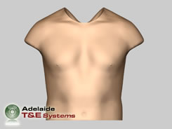
The Human Thoracic Surrogate (HTS) is a newly developed physical model, engineered to allow assessment of human injury. The HTS was conceived principally to quantify Primary Blast Injury (PBI) and measure the effectiveness of mitigation strategies, including Personal Protective Equipment (PPE) concepts.

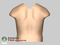
The HTS is designed to function as an anatomically correct mannequin incorporating a range of sensors selected to facilitate injury scoring. This injury scoring capability is paramount when conducting military human survivability and protection studies.

In response to the increased likelihood of military and civilian personnel incurring PBI, Adelaide T&E Systems has been working with Australia’s Defence Science and Technology Organisation (DSTO) to incrementally develop suitable surrogate technology to assess levels of PBI and the effectiveness of PPE concepts. The increase in risk of PBI is a consequence of the sharp rise in the use of the improvised explosive device (IED) and the emergence of military enhanced blast munitions.

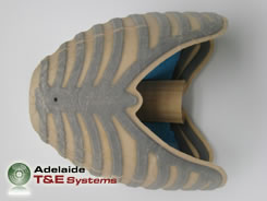
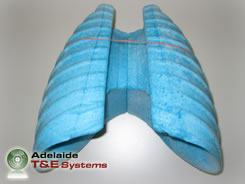
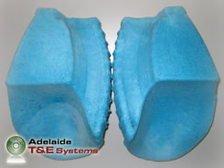
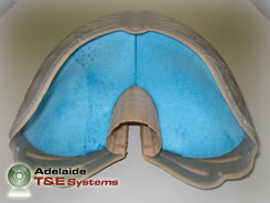
The HTS is the first anatomically accurate, biofidelic and re-usable human thoracic model. As such, it is well suited to assessing the protection efficacy of actual protective garments and equipments (most other surrogates are not human in shape). The synthetic materials developed to represent the various soft tissues within the HTS (e.g. muscles, organs etc) have similar physical characteristics to real human tissues, although do not degrade with time or vary significantly with temperature (as do gelatin based tissue simulants). By careful design, selection of materials, and testing, the response of the HTS to external loading is well correlated with human response.

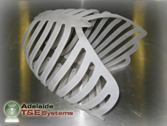
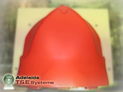
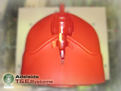
This third generation HTS model is dimensionally representative of the 50th percentile US Warfighter, and has been developed with complete Computer Aided Design (CAD) to facilitate the manufacture of all moulds and associated tooling. This scientific approach to manufacturing yields extremely accurate and consistent physical models whilst allowing the implementation of Finite Element Analysis (FEA).

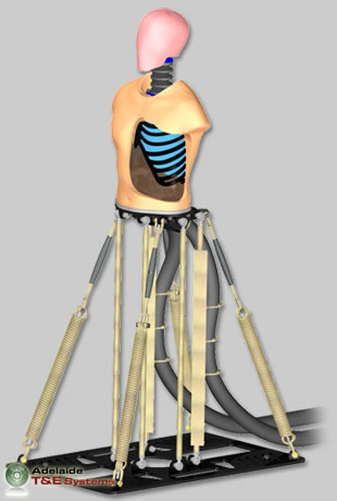
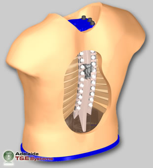
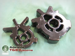
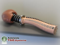
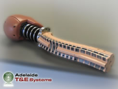
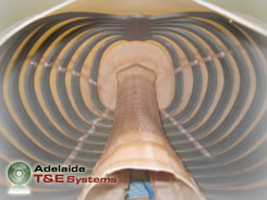
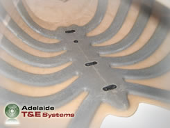
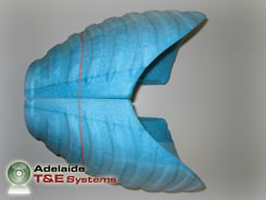
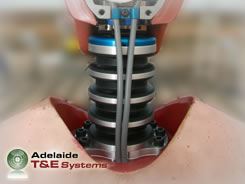
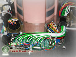
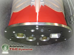
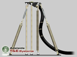
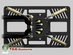
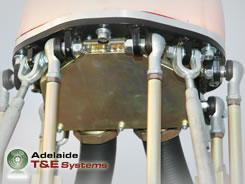
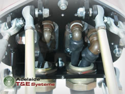
The HTS is compatible with the Hybrid III Crash Test Dummy head and neck (allowing the user to measure the effectiveness of head and neck PPE on the same physical model). The HTS assembly includes a spinal column (with all vertebrae), rib cage assembly, lungs, abdominal organ block and an exterior skin/soft tissue covering that can be removed to allow replacement or substitution of sensors and components. A dynamic HTS mounting system has also been engineered to allow movement under blast loading and vital instrumentation cable protection.

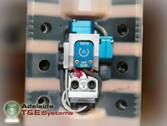
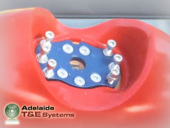
The HTS uses loadcells, accelerometers and pressure gauges to facilitate injury scoring. If used, accelerometers and loadcells within the Hybrid III Crash Test Dummy head and neck are electrically connected to the HTS via a wiring loom located within the spinal column. A custom 6-axis accelerometer cube is positioned at the rear of T6 vertebrae and also connects to the wiring loom within the spinal column. Additional accelerometers are located on the sternum and ribs, and pressure gauges on the sternum and lungs complete the sensor suite. Outputs from the sensor suite are used to generate injury scoring for up to six published injury criteria.


Spinal Assembly

The HTS spinal assembly is constructed from eighteen uniquely shaped rigid vertebrae bonded within a flexible elastomer. The elastomer portion of the spinal assembly has external protrusions that simulate anterior, posterior, medial and lateral ligament and muscular groups. The vertebrae are manufactured from polycarbonate using a high-pressure injection moulding technique, and contain a central hollow for cable passage. When assembled, there is a parallel disc space of 5mm between all vertebrae and the spinal curvature results from angulation within the vertebrae. At the rear of T6 vertebrae, a flat face containing metallic threaded inserts allows for the attachment of a custom designed, multi-axis, linear and rotational accelerometer mount. Cabling form these accelerometers can be routed back into the spinal cable passage, which transitions from 12mm to 20mm in diameter below T6 to allow for additional wires. Near the base of the spinal assembly on the medial and lateral surfaces of L3 and L4 vertebrae there are bores for cabling to exit and connect to relevant terminals on the connectors or circuit board.

HTS Vertebrae HTS Spinal Assembly HTS Spinal Assembly Accelerometer Mount

Thoracic Cage Assembly

The HTS thoracic cage assembly is constructed from a single tough and durable polycarbonate component, bonded between two layers of directional stretch fabric with an elastomer compound. The ribcage is CNC machined prior to being formed in a proprietary process (automated), which leaves the component in a fully annealed condition. The directional stretch fabric simulates the intercostal muscles that link ribs and influence thoracic motion, and is seamlessly bonded to the polycarbonate ribcage in a vacuum assisted laminating process. The ribcage geometry has been stylised to eliminate weak points whilst maintaining an overall stiffness that fits well within published human thoracic compression corridors. The thoracic cage assembly has attachment locations on the rear face of the sternum for accelerometers and pressure transducers that protrude through the sternum. Attachment of the thoracic cage assembly to the spine is achieve with nylon SHCS fasteners that pass through holes moulded in the vertebrae and engage in threads machined near the end of the ribs.

HTS Ribcage Assembly HTS Thoracic Cage Assembly HTS Thoracic Cage Assembly HTS Thoracic Cage Assembly
 

HTS Lungs

The HTS lungs are a symmetrical set manufactured from proprietary soft, light, open-celled elastomeric foam. The lung geometry represents a fully expanded organ (moment of inspiration) and has been sized to fill the space usually occupied by the heart. The exterior surface of the lung set shares the inner surface of the thoracic cage assembly and the diaphragm surface of the abdominal organ block, ensuring intimate contact. The lung surface also contains markings that identify standard anterior, posterior and lateral regions where pressure transducers can be positioned.

HTS Lungs
HTS Lungs
HTS Lungs
HTS Lungs
 

Abdominal Organ Block

The abdominal organ block is a soft fleshy mass of proprietary elastomer that simulates soft tissues contained within the abdomen. The abdominal organ block has a bottom face that is shaped to provide clearance for cabling, connectors and instrumentation PCB.

HTS Abdominal Organ Block
 

The Outer Skin/Soft Tissue Assembly

The outer skin/soft tissue assembly is a soft fleshy mass of proprietary elastomer that covers the spine, thoracic cage and abdominal block and has an external geometry representative of the 50th percentile US Warfighter. The skin/soft tissue assembly is available with an external covering of skin composed of a biological collagen matrix hydrated in another proprietary elastomer. The skin/soft tissue assembly is fixed in position by clamping ring that is actuated from beneath the HTS. Removal of the skin/soft tissue assembly allows rapid sensor replacement and inspection.

HTS Outer Skin/Soft Tissue Assembly HTS Outer Skin/Soft Tissue Assembly HTS Outer Skin/Soft Tissue Assembly HTS Outer Skin/Soft Tissue Assembly
 

Mounting Hardware

To attach a Hybrid III Crash Test Dummy neck to the HTS, an adaptor plate is conventionally fitted to the base of the Hybrid III neck. This plate can then be bolted (6 x M8 SHCS fasteners) to another plate that is attached to the HTS spinal assembly. The base of the spinal assembly is fastened to a large plate that also mounts a sensor PCB, electrical fittings and skin/soft tissue clamp. All of this hardware is CNC machined from aluminium and anodised for corrosion resistance. Alternatively, the Frangible Ballistic Head (FBH) could be attached in place of the Hybrid III head.

Hybrid III Neck
 

Dynamic HTS Mounting Rig

To ensure the HTS survives shock loading undamaged, it is paramount to allow some movement that in turn reduces restraint forces. To accomplish this, Adelaide T&E Systems has engineered the Dynamic HTS Mounting Rig. The Dynamic HTS Mounting Rig features a rugged steel construction with six parallel support columns that maintain a horizontal HTS mounting platform regardless of angular displacement. Resistance to motion is applied by four heavy duty tension springs that can be pre-loaded to varied tension with turnbuckles. A removable angled cover beneath the HTS mounting platform provides access to the electrical connections in the base of the HTS and in conjunction with the flexible large-bore conduits offers complete cable protection form shock waves and fragmentation. All components within the Dynamic HTS Mounting Rig are powder coated or electroplated to provide exceptional weather resistance.

Dynamic HTS Mounting Rig Dynamic HTS Mounting Rig Dynamic HTS Mounting Rig Dynamic HTS Mounting Rig
 
Adelaide T&E Systems
Adelaide T&E Systems © 2008 All Rights Reserved.